Save as PDF
Opens your browser print dialog — select "Save as PDF" to download.
EC-303 (GS)
B.Tech., III Semester
Examination, December 2023
Grading System (GS)
Digital System Design
Note: i) Attempt any five questions.
किन्हीं पाँच प्रश्नों को हल कीजिए।
ii) All questions carry equal marks.
सभी प्रश्नों के समान अंक हैं।
iii) In case of any doubt or dispute the English version question should be treated as final.
किसी भी प्रकार के संदेह अथवा विवाद की स्थिति में अंग्रेजी भाषा के प्रश्न को अंतिम माना जायेगा।
Design a full adder using only required number of half adders.
केवल आधे योजकों की आवश्यक संख्या का उपयोग करके पूर्ण योजक डिजाइन करें।
Design an Excess-3 to GRAY code convertor and obtain a minimum SOP form. Realise the function using 2-level gate implementation.
एक Excess-3 से GRAY कोड कन्वर्टर डिजाइन करें और न्यूनतम SOP फॉर्म प्राप्त करें। 2-स्तरीय गेट कार्यान्वयन का उपयोग करके फ़ंक्शन को समझाइए।
Design the logic circuit diagram of a 2-bit binary multiplier and represent the output in POS form.
2-बिट बाइनरी मल्टीप्लायर के लॉजिक सर्किट आरेख को डिजाइन करें और आउटपुट को POS फॉर्म में प्रस्तुत करें।
For the following Boolean function, list all prime implicants, essential prime implicants and POS form using K-map.
F(A, B, C, D) = ΠM (0, 1, 3, 4, 7, 9, 11, 14, 15)
निम्नलिखित बूलियन फ़ंक्शन के लिए, K-मैप का उपयोग करके सभी प्रमुख निहितार्थों, आवश्यक प्रधान निहितार्थों और POS फ़ॉर्म को सूचीबद्ध करें।
F(A, B, C, D) = ΠM (0, 1, 3, 4, 7, 9, 11, 14, 15)
Implement the following Boolean functions using 8 × 1 multiplexer (MUX) and external logic gates. Connect inputs 'B' and 'D' to select lines (S₁ and S₀) of MUX.
F(A, B, C, D) = Σm (0, 3, 5, 7, 9, 10, 12, 14)
8 × 1 मल्���ीप्लेक्सर (MUX) और बाहरी लॉजिक गेट्स का उपयोग करके निम्नलिखित बूलियन फ़ंक्शन को कार्यान्वित करें। MUX की चुनिंदा लाइनों (S₁, S₀) से इनपुट 'B' और 'D' कनेक्ट करें।
F(A, B, C, D) = Σm (0, 3, 5, 7, 9, 10, 12, 14)
Realize (A+A'B) using only minimum number of 2-to-4 line decoder to generate the function at a particular output pin of decoder.
डिकोडर के विशेष आउटपुट पिन पर फ़ंक्शन उत्पन्न करने के लिए केवल 2-to-4 लाइन डिक��डर की न्यूनतम संख्या का उपयोग करके (A+A'B) को समझाइए।
Implement the following Boolean functions using 8 × 1 multiplexer (MUX) and external logic gates. Connect inputs 'B' and 'D' to select lines (S₁ and S₀) of MUX.
F(A, B, C, D) = Σm (0, 3, 5, 7, 9, 10, 12, 14)
8 × 1 मल्टीप्लेक्सर (MUX) और बाहरी लॉजिक गेट्स का उपयोग करके निम्नलिखित बूलियन फ़ंक्शन को कार्यान्वित करें। MUX की चुनिंदा लाइनों (S₁, S₀) से इनपुट 'B' और 'D' कनेक्ट करें।
F(A, B, C, D) = Σm (0, 3, 5, 7, 9, 10, 12, 14)
Design a 3 bit UP/DOWN synchronous counter with mode bit M, such that when, M = 0, then counter counts in DOWN direction and when M = 1, then counter counts in UP direction. Use D flip flop for design of the counter.
मोड बिट M के साथ 3 बिट UP/DOWN सिंक्रोनस काउंटर डिज़ाइन करें, जैसे कि जब, M = 0, तो काउंटर DOWN की दिशा में काउंट किया जाता है और जब M = 1, तो काउंटर UP दिशा में काउंट किया जाता है। काउंटर के डिजाइन के लिए D फ्लिप-फ्लॉप का उपयोग करें।
A square waveform of 120 Hz is to be used to generate a square waveform of frequency 20 Hz using a counter. Design a logic circuit for the same using D flip-flops and other necessary logic gates. Show all the necessary steps for achieving the goal.
120 Hz की एक वर्ग तरंग का उपयोग करके 20 Hz आवृत्ति की एक वर्ग तरंग उत्पन्न करने के लिए 120 Hz के एक वर्ग तरंग रूप का उपयोग किया जाना है। D फ्लिप-फ्लॉप और अन्य आवश्यक लॉजिक गेट्स का उपयोग कर��े इसके लिए लॉजिक सर्किट डिज़ाइन करें। लक्ष्य प्राप्ति के लिए सभी आवश्यक कदम बताइए।
Convert a T flip-flop into J-K flip-flop. Show all the necessary calculations with final logic diagram.
एक T फ्लिप-फ्लॉप को J-K फ्लिप-फ्लॉप में बदलें। अंतिम तर्क आरेख के साथ सभी आवश्यक गणनाएँ दिखाए।
The state diagram of a control unit is shown in Fig. 1. It has four states and two inputs, 'x' and 'y'. Draw the equivalent ASM chart and design the controller using D flip flops.
एक नियंत्रण इकाई का स्टेट आरेख चित्र 1 में दिखाया गया है। इसमें चार स्टेट और दो इनपुट, 'x' और 'y' हैं। समतुल्य ASM चार्ट बनाएं और D फ्लिप-फ्लॉप का उपयोग करके नियंत्रक को डिजाइन करें।
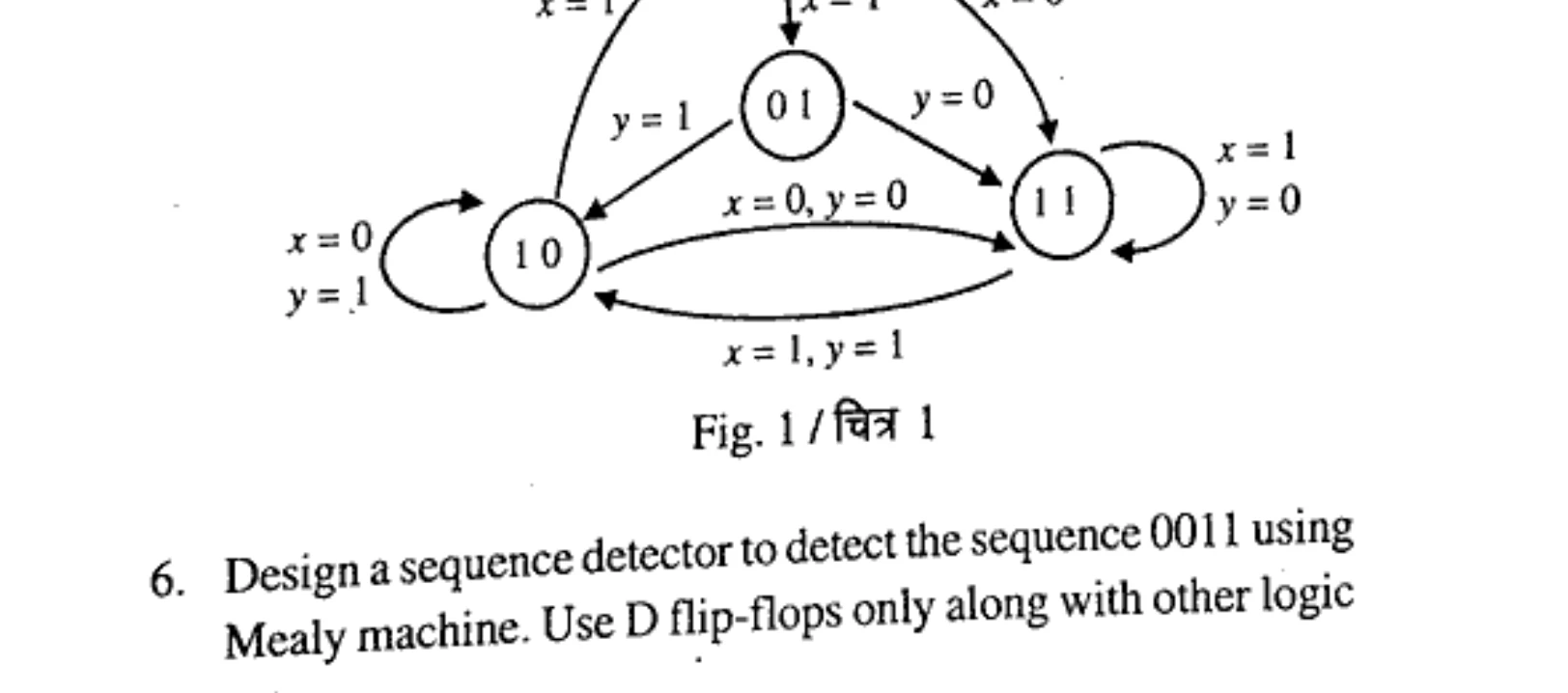
Fig. 1 / चित्र 1
Design a sequence detector to detect the sequence 0011 using Mealy machine. Use D flip-flops only along with other logic gates.
मीली मशीन का उपयोग करके अनुक्रम 0011 का पता लगाने के लिए अनुक्रम डिटेक्टर डिज़ाइन करें। D फ्लिप-फ्लॉप का उपयोग केवल अन्य लॉजिक गेटों के साथ ही करें।
Explain the following:
i) Three state TTL gate
ii) Fan-in and Fan-out
iii) Noise margin
निम्���लिखित को स्पष्ट करें:
i) थ्री स्टेट TTL गेट
ii) फैन-इन और फैन-आउट
iii) नॉइज़ मार्जिन
Design a synchronous counter to generate the following sequence (as shown in Fig. 2) using T flip flop.
T फ्लिप-फ्लॉप का उपयोग करके निम्नलिखित अनुक्रम (जैसा कि चित्र 2 में दिखाया गया है) उत्पन्न करने के लिए सिंक्रोनस काउंटर डिज़ाइन करें।
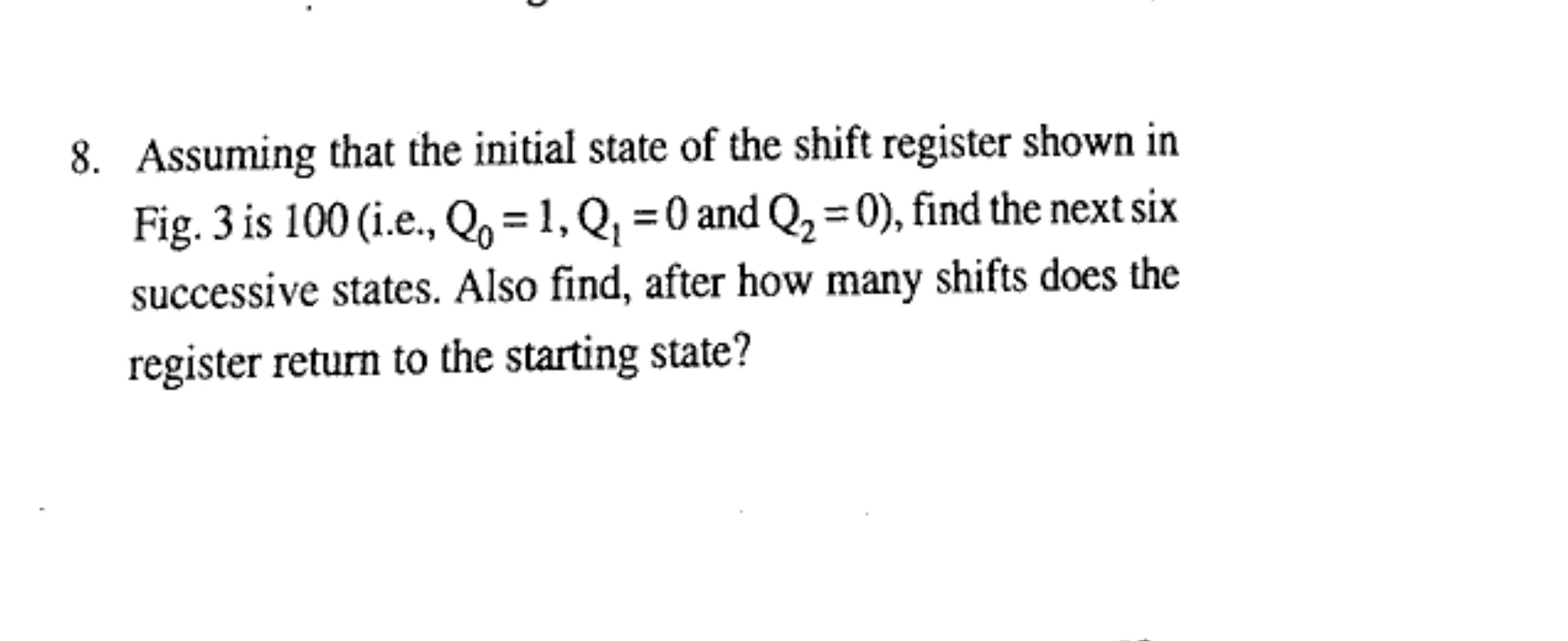
Fig. 2 / चित्र 2
Assuming that the initial state of the shift register shown in Fig. 3 is 100 (i.e., Q₂ = 1, Q₁ = 0 and Q₀ = 0), find the next six successive states. Also find, after how many shifts does the register return to the starting state?
यह मानते हुए कि चित्र 3 में दिखाए गए शिफ्ट रजिस्टर की प्रारंभिक स्थिति 100 है (i.e., Q₂ = 1, Q₁ = 0 और Q₀ = 0), अगली छह क्रमिक अवस्थाएँ ज्ञात कीजिए। यह भी पत�� करें कि कितनी शिफ्टों के बाद रजिस्टर प्रारंभिक स्थिति में वापस आ जाता है?
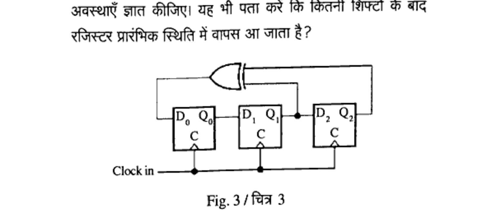
Fig. 3 / चित्र 3